Abstract
The fatigue crack growth depends on the dissipated energy at the crack tip and in this regard, different analytical and numerical models were proposed by many researchers to describe as the plastic work affect the fatigue material behaviour. Experimental tests can be carried out for evaluating the energy dissipated during the crack growth principally based on the hysteresis loop measurement. However, these techniques need of suitable equipment and set-ups and then find some restrictions if applied in-situ and on real components.
In this work, an experimental approach is used to obtain a thermographic parameter capable of describing the plastic work at the crack tip. The proposed approach is based on the phase shift of the thermal signal that occurs at the crack tip in the plastic area.
Two specimens of two different steels, austenitic and martensitic, were tested and monitored with an infrared camera to collect thermoelastic phase data. A similar correlation to the dissipated energy was obtained with the fatigue crack growth behavior of materials.
Introduction The fatigue crack growth depends on many factors related to the material and the micro-mechanisms that act at the crack tip. Paris and Erdogan (1963) firstly described the crack growth rate behavior as a function of the stress intensity factor (SIF) (1999). In particular, this latter and the crack growth are related through two constants of material that can be obtained by means of experimental tests according to Standards (2004). In the last years, many researchers focused their attention on energy-based approaches (Weertman, 1973; Klingbeil, 2003; Mazari et al., 2008; Kucharski et al., 2016; Ranganathan et al., 2008). Indeed, the dissipated energy plays a key role in the crack growth behavior and can be used to describe the plastic work at the crack tip. The energy-based approach, proposed firstly by Weertman (1973), links the crack growth rate with the critical energy to create a unit surface area. Similar results were obtained by Klingbeil (2003), where the crack growth in ductile solids is governed by the total cyclic plastic dissipation ahead of the crack. Mazari et al. (2008) starting from the Weertman’s and Klingbeil’s approach, developed a new model in which a similar Paris Law model was obtained between the crack growth and the heat dissipated per cycle. Different experimental approaches were used in literature focused on determining the critical energy by means of strain gages in the plastic zone, Ranganathan et al., (2008), calorimetric measurements, Ikeda et al., (1977) and hysteresis loop evaluation, Mazari et al., (2008). More recently, thermographic techniques were used aiming to determine the heat sources at the crack tip in the cyclic plastic zone (Carrascal et al., 2014; Cui et al., 2015; Meneghetti et al., 2016; Ancona et al., 2016; Palumbo et al., 2017). Infrared Thermography (IRT) is a full-field contactless technique used in many fields such as, non-destructive testing (NDT), process monitoring and evaluation of heat sources during fatigue tests. In particular, many approaches are present in literature in which the IRT technique is used for investigating the fatigue behaviour of steels (Meneghetti, 2007; Palumbo et al., 2017; De Finis et al., 2019). Less works regards the monitoring of the fatigue crack growth. In particular, a temperature rise due to the heat dissipations can be observed around the crack tip where the plastic zone is located. In this regard, Carrascal et al., (2014) used IRT for evaluating the Paris Law constants of a polymer (polyamide) with an experimental methodology. A good agreement was found with respect to traditional calculation methods. Cui et al. (2015), applied IRT to study the fatigue crack growth of magnesium alloy joints and demonstrated the potential of IRT in predicting the threshold value for unstable crack growth. In the work of Meneghetti et al. (2016), experimental tests were performed for evaluating from temperature measurements the specific heat energy per cycle averaged in a small volume surrounding the crack tip. The above exposed procedures are based on temperature data and can find limitations in some applications in which the temperature changes due to the plastic work are very low. This is the case of brittle or materials with high diffusivity. In this regard, Palumbo et al. (2017) presented a new procedure based on the processing of thermographic signal in the frequency domain. In particular, the harmonic of the temperature signal at the twice of the loading frequency has been used to estimate the heat dissipated at the plastic area. Interesting results in assessment of plastic zone and SIF were obtained by using the Thermoelastic Stress Analysis (TSA) (Dulieu-Barton, 1999; Pitarresi et al., 2003; Wang et al., 2010; Harwood et al., 1991; Stanley, 1997; Dunn, 1997; Dulieu-Smith, 1995). By knowing the sum of the principal stresses, it is possible to determine the stress intensity factor, and at the same time, it is possible to determine the crack growth rate by analyzing the phase data (Tomlinson et al. 1999; Tomlinson et al., 2011; Diaz et al., 2004; Diaz et al., 2004). In this regard, Ancona et al. (2015, 2016) proposed an automatic procedure based on TSA, to assess the Paris Law constants and to study the fracture behaviour of 4 stainless steels. In this work, the thermoelastic phase signal has been used as an index for monitoring the energy dissipated at the crack tip and then the fatigue crack growth behaviour of two steels: AISI 422 and CF3M. Two CT steel specimens were used and tested according to ASTM E 647-00 and the monitoring of crack tip growth was performed in a continuous manner by means of a cooled IR camera. Thermal data were processed in the frequency domain in order to extract the thermoelastic phase signal related to the energy dissipated at the crack tip. Similar relations were obtained between the crack growth, the phase signal and the energy dissipated per cycle and the capability of the phase signal in describing the fatigue crack growth has been demonstrated.
2. Theory In absence of material phase transitions, the response of a material to a mechanical cyclic excitation, in presence of dissipative intrinsic processes involves a hysteresis loop due to phenomena producing energy dissipations. Considering a cyclic test, in load control, these phenomena determine a retardation of the strain with respect to the imposed stress, here indicated as ‘ψ’, Figure 1a, De Finis et al., (2019). For assessing and quantifying the energy of internal friction, viscoelasticity and micro-plasticity one can refer to dumping phenomena (). A common procedure involves the study of the area under a generic hysteresis loop. In Figure 1b, is depicted a hysteresis loop at the most general loading ratio to which all the cases can be referred (R=-1), in presence of non-adiabatic deformation process, the figure also reports the completely elastic behaviour of the materials which is represented by the line k-h.
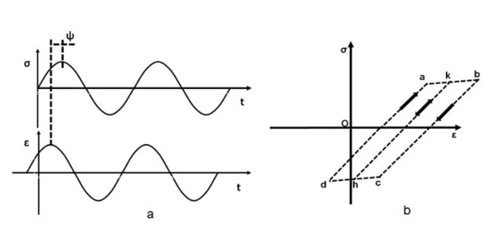
Fig. 1. Phase shift between strain and stress during (a) fatigue loading and (b) a generic hysteresis loop, De Finis et al., (2019).
Although the test is running at a stress ratio different from -1, generally, the onset of damage phenomena leads to a local change of stress ratio, so that certain zones of the material may undergo tension-compression conditions due to the plasticisation. For this reason, in presence of damage, it is possible to refer to the case of full-inversion conditions (R=-1) as the most general case. The model of figure 1b, however, disregards some aspects related to kinematic and isotropic hardening47. In these conditions, in fact, the study of the viscos-plastic behaviour is described by a simple relation between stress and strain and the energy of dissipative processes can be somehow quantified by calculating the area of hysteresis loop (Ap) which is, in turn, related to the phase shift between strain and stress, ‘ψ’. By focusing the attention on the energy involved in the process, the dissipative phenomena (e.g. viscous or plastic phenomena) occurring in the lattice in a fixed finite continuous volume of an isotropic and homogenous material ‘Vp’, can be described by using the first principle of thermodynamics, De Finis et al., (2019):
where ‘Wp’ is the supplied mechanical energy, ΔU’ is the internal energy per cycle variation due to microstructural rearrangements, to the formation of persistent slip bands and to all the phenomena related to irreversible dislocation movement in the lattice. A portion of this energy does not remain under mechanical form but converts into heating, in particular, it contributes to the irreversible heat source development in the material and, furthermore, it affects the temperature growth. The term ‘Q’ represents the heat exchanges (radiation, conduction, convection) which may be totally ascribed to heat conduction between the regions of the sample. The term ‘Ep’ refers to the mechanical work introduced in the material system during the plastic phenomena that is a portion of internal energy ‘ΔU’. As said before, it is correlated to irreversible changes of shape of the material. ‘Ed’ is the energy per cycle dissipated as heat. It includes the irreversible dissipative phenomena generated by the intrinsic heat sources (related to plastic phenomena) or internal energy variation (related to viscous phenomena) producing thermal effects De Finis et al.,